Technology Overview
Inez Power LLCs’ proprietary and patented Energy-from-Waste process utilizes Advanced Thermal Treatment Technologies (gasification). Inez Power LLCs’ environmentally engineered gasification method dramatically transforms solid waste of all types, primarily MSW (trash), by converting it into a combustible gas (“syngas”), which is the primary post-process output. The creation of this combustible gas is at the heart of Inez Power LLCs’ ability to generate utility- scale levels of clean, safe, renewable electrical power.
Inside a rotary kiln (a proprietary design of the Company), Inez Power LLCs’ unique process converts the feedstock waste materials such as MSW, wood construction debris, lawn waste, etc., into a combustible, BTU-rich gaseous fuel or syngas. The process design also sterilizes the nonorganic side-stream by-products, yielding sellable recyclables (ferrous and non-ferrous metals, ceramics, etc.). Inez Power LLCs’ process is specifically designed to phase change the waste (solid to gas) in a unique “starved air” environment, which dramatically improves the quality of the downstream air emissions (at various points the temperatures are maintained below aluminum’s vaporization threshold, therefore reclaiming 100% of all metals including aluminum). The syngas is ducted to an INEZ POWER designed boiler and furnace—also proprietary designs of the company— which combust the syngas, converting its thermal energy into steam. The final phase in the conversion process is to input the steam into a turbine generator for the production of clean, safe and renewable utility-scale electrical power.
Due to the remarkable efficiency of the INEZ POWER process, virtually one hundred percent of the incoming waste stream is monetized as either clean, renewable, utility-scale electrical power, or as sellable recyclables. All of the ferrous and non-ferrous metals and glass are recovered at the end of the process. The final remaining output is a granular residue (non-toxic, non-hazardous mineral frit containing less than five percent carbon) that is an acceptable concrete additive.

Process in Detail
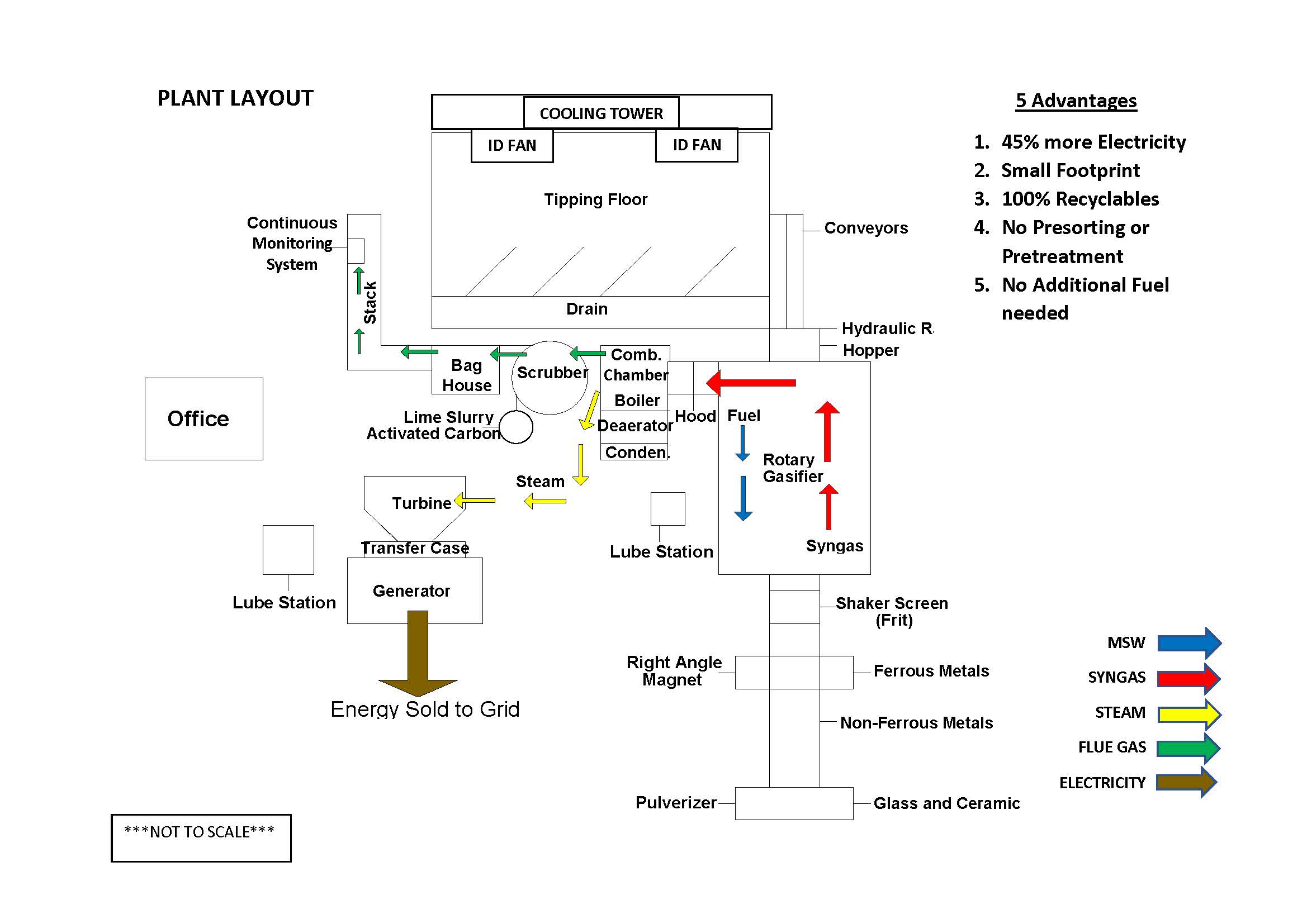
Inez Power LLCs’ proprietary method begins with the solid waste being deposited onto a tipping floor where it is temporarily stored. A rotary kiln is located downstream of the receiving hopper. The feedstock is fed into the rotary kiln via a hydraulic ram.
The patented and modified rotary kiln is pre-heated to a temperature slightly in excess of 600°F (Note: once the Gasifier kiln reaches operating temperature it is self sustaining and does not require additional heat inputs). A motorized drive system rotates the kiln at a designated revolution per minute rate; however, the operations manager may rotate the kiln at different speeds based on a number of calculated variables. Transit time inside the kiln is approximately 45 minutes. The syngas created inside the kiln is then ducted to a reduction chamber which functions as a destruction mechanism for the elimination or reduction of volatile organic compounds (VOC’s), hydrocarbons, dioxins, furans and other extraneous gases and compounds present in the initial syngas. Similar to the kiln, prior to process start-up the reduction chamber is heated to a temperature of at least 1600°F and its internal temperature is then maintained between 1600°F and 2400°F.
Managing the temperature of the gases exiting the rotary kiln and going to the reduction chamber is critical for maximum process efficiency and at least one of the following may be adjusted by a programmable logic controller in order to ensure consistent temperature: the feed rate of the waste entering the kiln; the rotation speed of the kiln; and/or the amount of air flow into the interior of the INEZ POWER gasifier kiln.
Upon exiting the reduction chamber the hot exhaust gases enter the INEZ POWER proprietary boiler where the thermal energy is used to create steam that can be used for power generation or a multitude of other commercial purposes.
The syngas is then passed through at least one air pollution control unit in which constituents, such as residual VOC’s, along with particulate matter, are removed (Note: In the initial design there are three air pollution control units, namely a reduction chamber, a spray dryer absorber, and a bag house; there may be more or fewer air pollution control units incorporated into the system depending on local air quality requirements). In the spray dryer absorber, the off-gases are treated to remove any remaining acids and metals that might be present. A slurry of lime and activated carbon is injected into the top of the spray dryer absorber unit for this treatment. Spent carbon and other particulate matter that may be generated at the spray dryer absorber are collected at the bottom of the absorber and transferred via a conveyor to a fly ash bin. From the spray dryer absorber the off-gases are ducted to a multi chamber bag house for the final removal of any remaining contaminants. Although the current bag house design has four chambers, it may contain any number of chambers in accordance with engineering designs and/or local regulatory requirements. Inside the bag house, the gases pass through filters to remove particulate matter. Particulates, including the ash collected inside the bag house are transported by conveyor belt to the fly ash bin. Finally, the resulting stack gases are discharged into the atmosphere and continuous emission monitors record the air quality of the emissions. Emissions from the stack constantly measure <0.5 on a 0 - 10 opacity scale (0 = clear) and have proven to be consistently below acceptable regulatory limits.
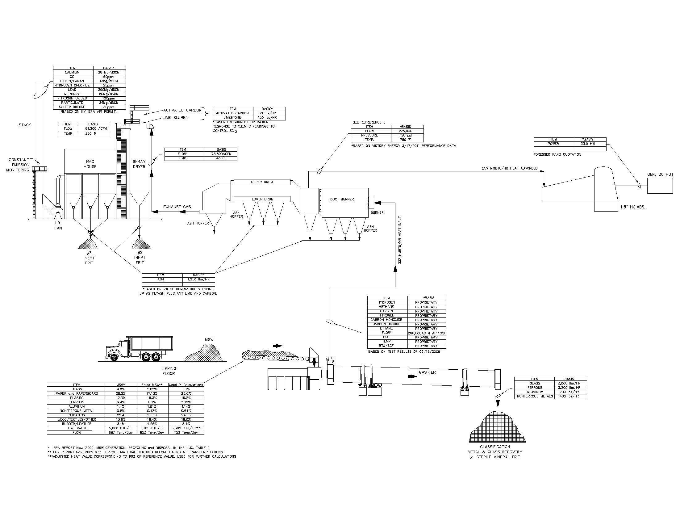
With Inez Power LLCs’ proprietary and permitted process, virtually 100% of the solid waste input is converted into thermal energy (steam), clean, renewable, utility scale electrical power, and recycled in an environmentally-beneficial manner. Additional information is contained in the accompanying engineering drawing and heat balance schematic.

Readiness and Reliability of Technology
Existing Plant(s)
Name: Inez Power LLC, Location: Debord, Kentucky.
Permit: Fully permitted operational facility.
Years/hours of operation: INEZ POWER received final air quality and operations permit in November 2009. Initial developmental operations began in 2003.
Feedstock types: MSW
Design capacity: 440 tons per day (as permitted by State of Kentucky) Annual throughput: NA *
Annual operating hours: NA *
Power generation: Steam/Electricity. Owner/operator: Inez Power LLC
* Important Note: While having been utilized as a demonstration facility, the existing
INEZ POWER plant has successfully run in excess of 2,000 hours. It has also been operated at its full 440 tons per day, 24/7 capacity, although not continuously. The plant is currently
being prepared for interconnection to the electric grid with an estimated completion date in the summer of 2011, when it will begin daily, 24/7 operations at its designed capacity.
Process Capability
Modularity: The INEZ POWER design is modular, based on discrete 750 TPD INEZ POWER Gasifiers.
Scalability: The components of the process can be scaled up by adding INEZ POWER Gasifiers in 750 tons per day increments. In addition, the gasifier-kiln can be adjusted to operate at different throughput rates (lower than 750 tons per day) as the amount of feedstock supply varies.
Ideal Operating Size: Inez Power LLCs’ internal analysis has determined the process reaches peak cost and operational effectiveness beyond 750 TPD and in increments thereof (e.g. 1500 tons per day equals two 750 tons per day modules, 3000 tons per day equal four 750 tons per day modules). The relative economics on the revenue side dramatically increase as a system is scaled from 750 to 1500 to 3000 tons per day. However, the capital requirements only incrementally increase, demonstrating the relative benefits in the economy of scale.
Material and Energy Balance (Separate Engineering Document Attached)
Conversion efficiency: virtually 100% of MSW is either consumed by the process (+90%) or presented as recyclable products (+10%)
Energy generation: Approximately .8 to 1.0 MW per ton of feedstock (Important Note: energy yield is entirely dependent on BTU value and moisture content of the MSW feedstock)
Plant Wide Efficiencies
Energy input – Minimal. Once the system is put in process – meaning all components are brought to operating temperature – the process is self sustaining.
Gross power generation – .8 to 1.0 MW per ton of fuel (Note: based on BTU and moisture content of MSW feedstock).
Parasitic load – 5% (estimated).
Net electricity generated – .7 to .9 MW per ton of feedstock.
Total plant wide losses in BTU/ton or kWh/ton – Included in parasitic load.
Emissions – Monitoring points are located at the reduction array and final stack. Emission control consists of a spray absorber and bag house.
Site Requirements – Actual plant footprint will be 3-5 acres (approximately 1.2-2 hectares)
– depending on design capacity. Additional land may be required for vehicular staging, setbacks or buffering, depending on local regulations.
By-Products – Metals (primarily steel and aluminum) and frit suitable for aggregate.
Summary
The Basic Process -
- Raw unprocessed waste is delivered to the Tipping Floor and is moved on to the
Process Ram.
- The waste then passes the material on to the INEZ POWER Gasifier for the actual heating and gasification
- The two Gasifier output streams are: 1) Syngas, which is sent to the Reduction Array
and 2) solids, which include sterile aluminum and steel; glass; and sterile mineral frit.
- The Reduction Array adds fresh air and ignition to combust the syngas at a proprietary temperature and time required to destroy any undesirable components and in so doing raises the flue gas temperature going to the Waste Heat Boiler.
- The Boiler turns the heat in the flue gas from the furnace into useful energy in the form of high-pressure, superheated steam, that can be used for generating electricity.
- An off-gas from the boiler is monitored by a Constant Emissions Monitoring System. Additionally, the monitoring meters the activated charcoal and lime slurry at the Spray Absorber for the removal of any remaining undesirable components in the gas stream.
- Cooler exhaust gases are sent to the Bag House for final removal of remaining particulates.
- A controlled ID Fan sends final process exhaust to the Stack. Constant emissions monitoring provides final control of stack Inert frit can be used as concrete additive.
ADVANTAGES OVER CURRENT TECHNOLOGIES
INEZ POWER has the following unique characteristics over other waste-to-energy technologies:
The INEZ POWER process utilizes a low-temperature, controlled environment in its proprietary INEZ POWER Boiler and Gasifier cell. This lower temperature and controlled environment minimizes pollutants and is below the aluminum vaporization. The byproducts are outputted 100% sterile and classified and separated for recycling.
High volume and minimally processed raw waste feedstock optimizes the process, reducing the necessity for handling or pre-processing and pre-treatment of MSW.
Utility-scale power production capabilities are achieved by energy-from-wasteUltra-low environmental emissions are achieved and demonstrated by full US government EPA compliance. A low temperature, controlled environment, minimizes HCL, NOx and SO2. Additionally, CO and CO2 are also below strict compliance levels.
